Overzicht
Eenanker flensis een pijpleidingcomponent die wordt gebruikt om axiale en andere ontwerpbelastingen van de pijp over te brengen naar een ankerblok, structuur of bevestigingssysteem. In tegenstelling tot gewone geschroefde pijpflenzen, worden veel ankerflenzen op projectbasis ontworpen en vervaardigd volgens een goedgekeurde tekening.
Waarom het belangrijk is voor pijpcomponenten
Het onderdeel kan drukeindbelasting, thermische uitzettingsbelasting, installatiebelasting, bodeminteractiebelasting en andere combinaties dragen die zijn gedefinieerd door het pijpleidingontwerp. Een catalogusdiameter en materiaalkwaliteit zijn niet voldoende om de geschiktheid vast te stellen.
De ankerflens, lasuiteinden, aangrenzende buis, wapening, betonnen of structurele bevestiging, corrosiebescherming en installatievolgorde moeten als één systeem worden ontworpen.
Methoden, parameters of proces
Maak een technisch gegevensblad op voordat u een offerte aanvraagt.
| Parameter | Vereiste projectinput |
|---|---|
| Ontwerpcode | Pijpleiding of leidingcode en lokale vereisten |
| Ontwerpvoorwaarden | Druk, temperatuur, levensduur en vloeistof |
| Ladingen | Axiale, buig-, schuif-, torsie-, vermoeiings- en installatiebelastingen, indien van toepassing |
| Pijpgegevens | OD, wand, materiaal, naadtype, toleranties en corrosietoeslag |
| Geometrie | Totale afmetingen, ankerring, naven, overgangen en laseinden |
| Materiaal | Volledige specificatie, kwaliteit, warmtebehandeling en taaiheidsvereisten |
| Analyse | Goedgekeurde spannings- of eindige-elementenbasis waar vereist |
| Inspectie | UT, MT/PT, mechanische tests, impacttests, hardheid en maatvoering zoals gespecificeerd |
| Coating | Begraven servicecoating en veldverbindingslimieten |
| Documentatie | Berekeningen, tekeningen, MTR's, BDE en vrijgaverecords |
Geef een op maat gemaakte ankerflens niet weer als in overeenstemming met ASME B16.5 of een andere flensnorm, tenzij het document dat onderdeel daadwerkelijk behandelt en het ontwerp is geverifieerd.
Verificatieopmerking:elke belastingswaarde, afmeting, materiaalvereiste en acceptatiecriterium moet afkomstig zijn van de projectingenieur of goedgekeurde tekening.
Leveranciers- en inspectiechecklist
- Bevestig de laatste goedgekeurde tekeningrevisie.
- Controleer de grondstoffenroute en de traceerbaarheid van de warmte.
- Controleer de smedenreductie, warmtebehandeling en testlocaties indien gespecificeerd.
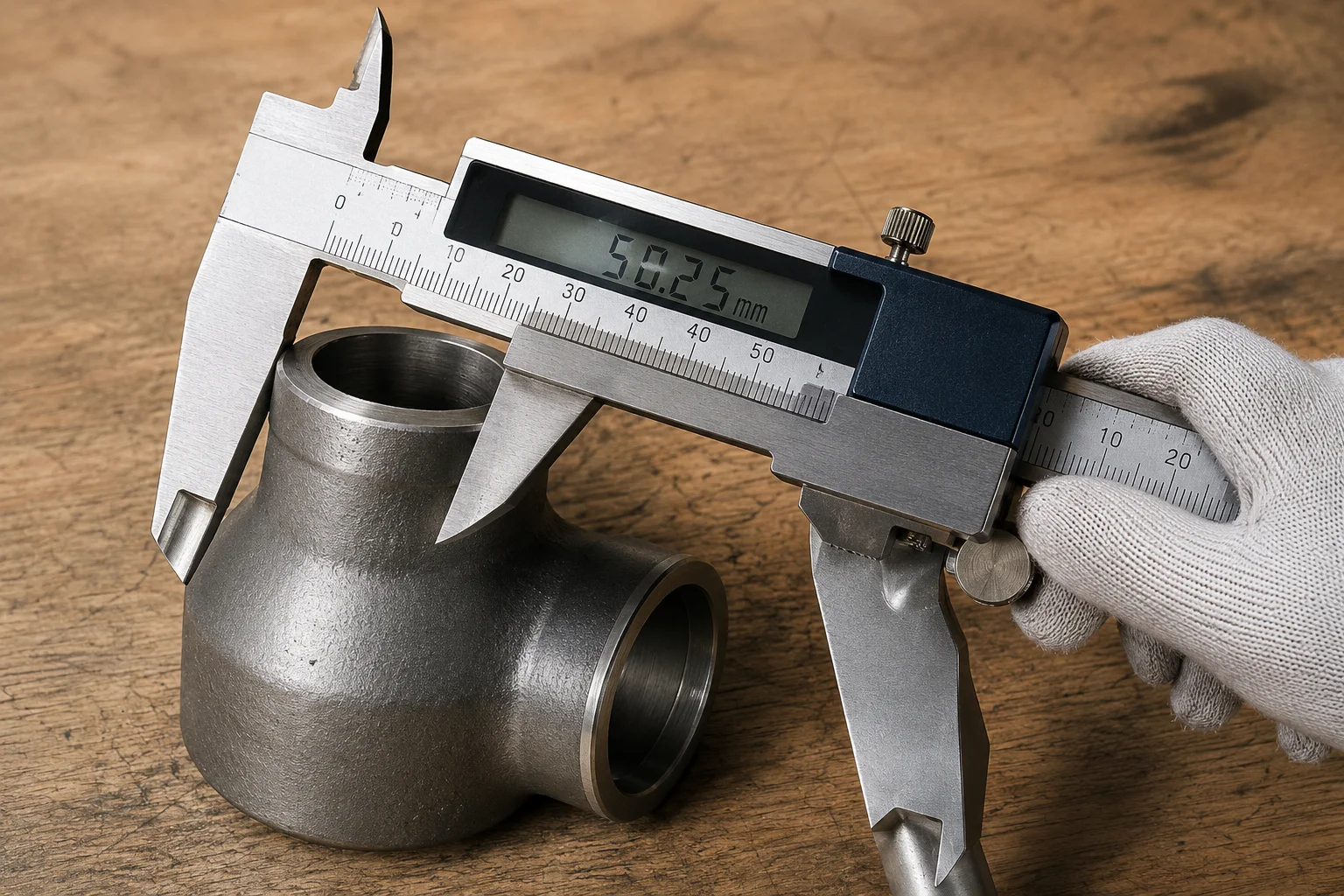
- Inspecteer de afmetingen van het lasuiteinde en de overgangsradii.
- Voer de vereiste volumetrische en oppervlakte-BDE uit.
- Controleer de maatvoering, concentriciteit en rechtheid.
- Controleer de hechting van de coating en voer vakantietests uit indien nodig.
- Bevestig markering, gewicht, hijspunten en verzendondersteuning.
Toepassing op pijpfittingen, kleppen en flenzen
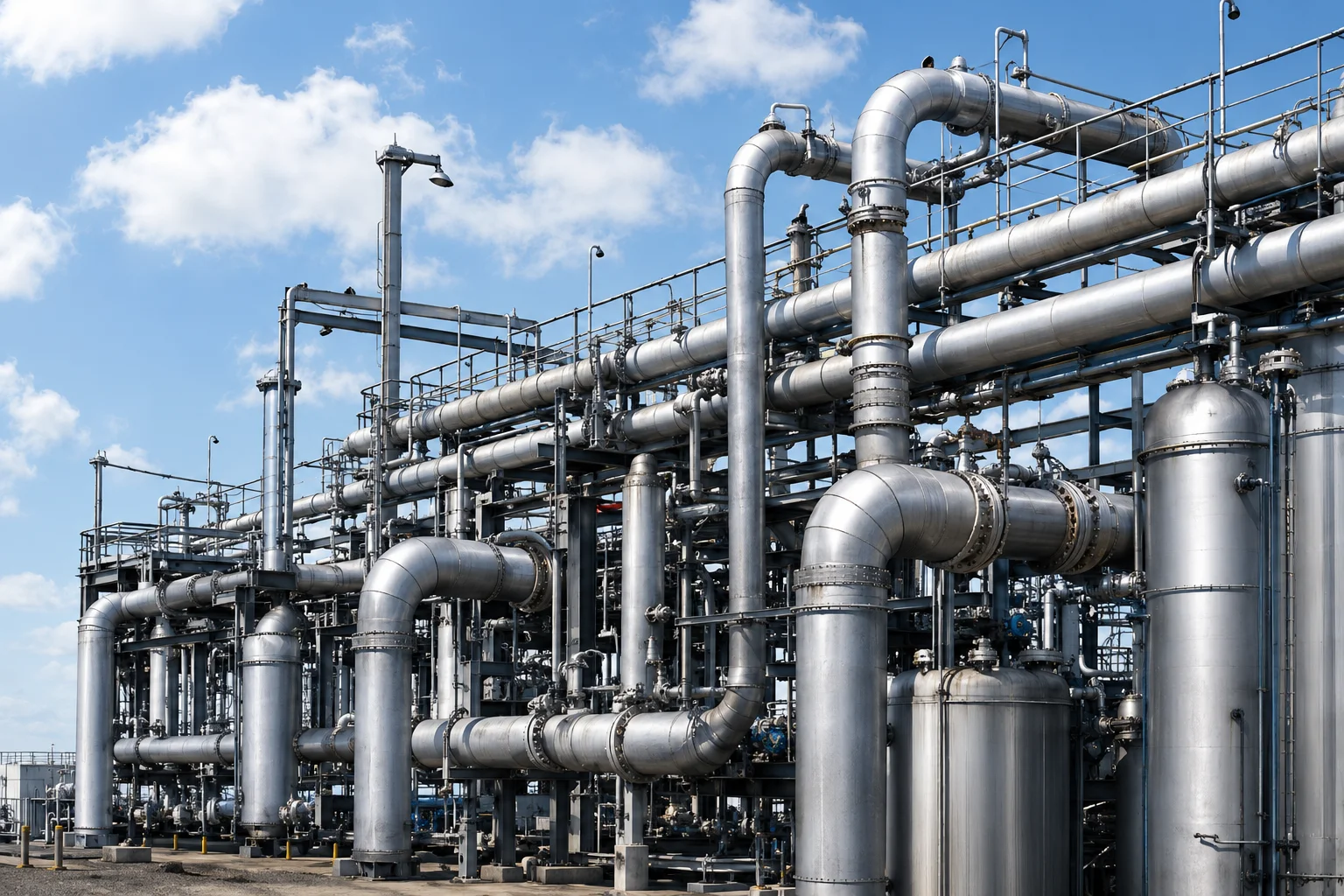
Ankerflenzen worden gebruikt in pijpleidingen, compressorstations, meetstations, tankaansluitingen, stijgleidingen en beveiligde kruisingen. Ze kunnen in de lijn worden gelast en in beton worden ingebed of worden verbonden met structurele beperkingen.
Het onderdeel kan de aangrenzende leidingspanning beïnvloeden. Installatietoleranties en veldlassen moeten worden opgenomen in de ontwerpbeoordeling.
Veelgestelde vragen
Is een ankerflens hetzelfde als een standaard lasnekflens?
Nee. Een ankerflens heeft een lastoverdrachtsfunctie en wordt doorgaans gemaakt volgens een projectontwerp. Een standaard lasnekflens is in de eerste plaats een geboute leidingverbinding.
Kan een leverancier een ankerflens alleen op basis van druk op maat maken?
Nee. Druk is slechts één belasting. Thermische, bodem-, structurele, installatie- en vermoeiingsbelastingen kunnen ook van invloed zijn.
Welk materiaal wordt normaal gesproken gebruikt?
Het materiaal is afhankelijk van de buiskwaliteit, ontwerptemperatuur, lasbaarheid, taaiheid, corrosieomgeving en projectspecificatie.
Moeten berekeningen in de inkooporder worden opgenomen?
De verantwoordelijkheid voor ontwerpberekeningen moet duidelijk worden toegewezen. De goedgekeurde teken- en ontwerpbasis moet deel uitmaken van het gecontroleerde pakket.
Volgende stappen
Vraag niet alleen naar de prijs. Stuur de ontwerpbasis, belastingen, leidinggegevens, goedgekeurde tekening, materiaalvereisten, BDE-plan, coatingsysteem, documentindex en verantwoordelijkheidsmatrix.
Vraag een offerte aan