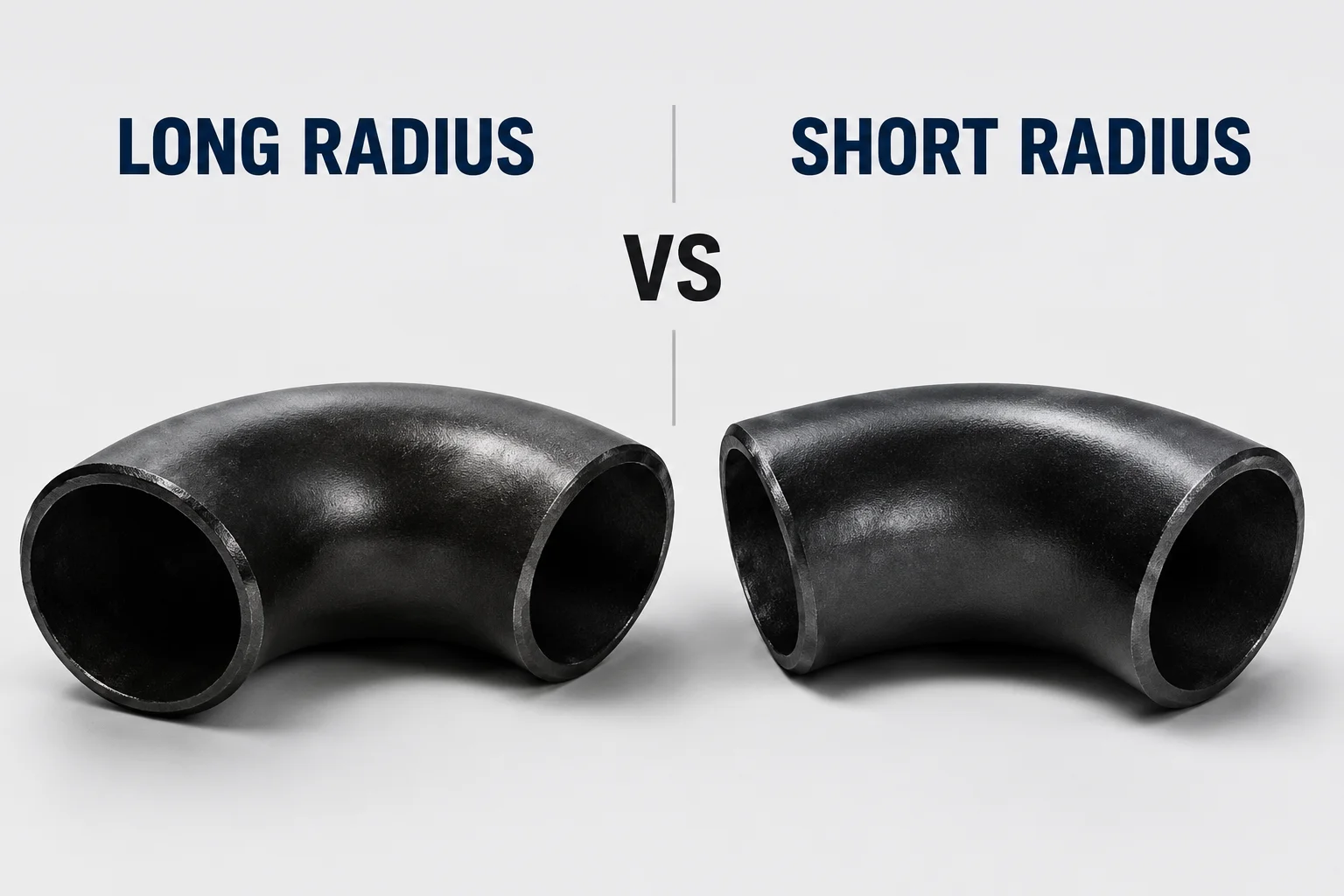
Panoramica
La differenza infaccia rialzata vs flangia a faccia piattagiunti è la geometria della sede della guarnizione. Una faccia sollevata ha un'area di contatto rialzata definita. Una faccia piatta è sostanzialmente piatta lungo la faccia della flangia. La scelta corretta dipende dallo standard della flangia, dal design dell'apparecchiatura, dal sistema di guarnizioni, dalla bullonatura e dalle specifiche del progetto.
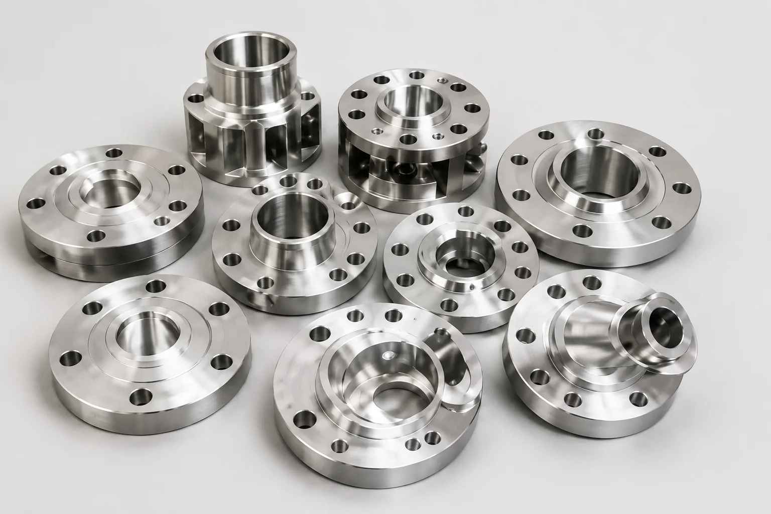
Perché è importante per i componenti delle tubazioni
La geometria della facciata modifica il modo in cui il carico del bullone viene trasferito attraverso la guarnizione e la flangia. Una connessione RF-FF non controllata può creare problemi di flessione o sollecitazione eccessiva, soprattutto con alcune apparecchiature di fusione. I fori dei bulloni corrispondenti non dimostrano la compatibilità.
La selezione del rivestimento deve essere risolta prima di ordinare valvole, pompe, filtri e bobine fabbricate.
Metodi, parametri o processo
Confrontare il giunto come sistema.
| Fattore | Volto sollevato | Faccia piatta |
|---|---|---|
| Contatto di guarnizione | Area rialzata definita | Ampia area frontale secondo il disegno del giunto |
| Designazione comune | RF | FF |
| Dimensioni della guarnizione | Deve corrispondere all'area salotto rialzata e allo standard | Deve corrispondere alla disposizione e allo standard della faccia piatta |
| Interfaccia dell'apparecchiatura | Comune su molti sistemi di flange in acciaio | Spesso specificato per apparecchiature o sistemi di materiali particolari |
| Revisione dell'assemblea | Altezza frontale, finitura, guarnizione e carico dei bulloni | Planarità, copertura della guarnizione, limiti dell'attrezzatura e carico dei bulloni |
| Giunto misto | Richiede una revisione tecnica | Richiede una revisione tecnica |
Non levigare una superficie sollevata o aggiungere una disposizione speciale della guarnizione senza una procedura di riparazione o modifica approvata. La lavorazione può modificare lo spessore, la geometria, le ipotesi di classificazione e la marcatura.
Nota di verifica:confermare le dimensioni esatte del rivestimento e la finitura superficiale dallo standard della flangia richiesto dal contratto e dal disegno dell'attrezzatura.
Lista di controllo dei fornitori e delle ispezioni
- Verificare il rivestimento su entrambi i componenti di accoppiamento.
- Confermare il tipo, le dimensioni, lo spessore e il materiale della guarnizione.
- Esaminare i limiti del produttore dell'apparecchiatura.
- Ispezionare la planarità della faccia e i danni alla superficie.
- Confermare il materiale di bullonatura e la procedura di serraggio.
- Controllare se qualche distanziale, kit isolante o guarnizione speciale modifica il giunto.
- Ottenere l'approvazione tecnica per disposizioni miste RF/FF.
- Registrare qualsiasi lavorazione o riparazione del rivestimento.
Applicazione a raccordi per tubi, valvole e flange
I giunti frontali rialzati sono comuni su molti sistemi di tubazioni in acciaio. I giunti a faccia piatta vengono utilizzati in sistemi di flange specifici e su alcune apparecchiature. La disposizione corretta è definita dalla classe delle tubazioni dell'impianto e dalle specifiche dell'apparecchiatura.
Per valvole e pompe, l'ordine di acquisto deve indicare esplicitamente il rivestimento richiesto. Non accettare il "volto standard" quando il fornitore utilizza un sistema standard diverso.
Domande frequenti
Una flangia RF può essere fissata direttamente a una flangia FF?
Solo dopo che la revisione tecnica avrà confermato che il giunto è accettabile per i materiali, la guarnizione, l'attrezzatura, i carichi e il codice applicabile.
Sulle flange FF viene sempre utilizzata una guarnizione integrale?
La disposizione della guarnizione deve seguire il disegno del giunto e le specifiche di progetto. Evitare presupposti universali.
È possibile eliminare la faccia sollevata?
Solo nell'ambito di una procedura di progettazione e riparazione approvata che confermi le dimensioni rimanenti e l'idoneità.
Quale rivestimento sigilla meglio?
Le prestazioni di tenuta dipendono dal giunto completo: rigidità della flangia, finitura superficiale, guarnizione, bullonatura, allineamento e assemblaggio.
Passaggi successivi
Controllare la classe dell'ugello e della tubazione dell'apparecchiatura prima di acquistare le flange di accoppiamento. Emettere uno schizzo congiunto ogni volta che le due parti provengono da standard o produttori diversi.
Richiedi un preventivo