Tổng quan
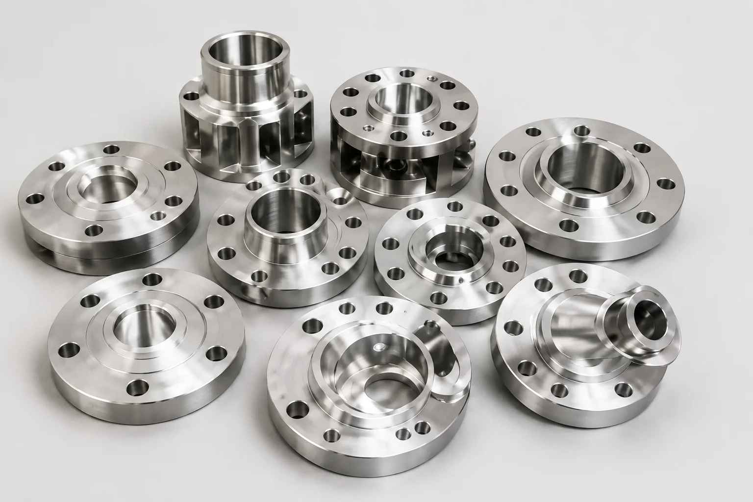
Mặt nâng và mặt phẳng mô tả hình học tiếp xúc đệm của mặt bích. Mặt nâng lên tập trung chỗ đệm đệm vào khu vực hình khuyên bên trong vòng tròn bu lông. Mặt phẳng mở rộng bề mặt tiếp xúc được gia công trên toàn bộ mặt bích. Bề mặt chính xác được xác định bởi tiêu chuẩn mặt bích, vật liệu, thiết kế thiết bị, hệ thống đệm và thông số kỹ thuật của dự án.
Mặt bích RF và mặt bích FF không thể thay thế cho nhau. Bề mặt phải được bao gồm trong đơn đặt hàng vì cùng kích thước danh nghĩa và loại có thể được cung cấp với các tùy chọn bề mặt khác nhau trong đó tiêu chuẩn quản lý cho phép chúng.
Tại sao nó quan trọng đối với các thành phần đường ống
Bề mặt ảnh hưởng đến diện tích tiếp xúc của miếng đệm, sự phân bố tải trọng của bu lông, sự xoay của mặt bích và nguy cơ gây ứng suất quá cao cho các bộ phận giòn. Mặt bích thép mặt nâng được nối trực tiếp với bộ phận bằng sắt xám mặt phẳng có thể tạo ra điều kiện tải trọng bất lợi trừ khi mối nối được thiết kế và phê duyệt đặc biệt.
Lựa chọn miếng đệm phải phù hợp với mặt. Vòng đệm nằm bên trong bu lông thường có mặt nhô lên. Một miếng đệm toàn mặt trải dài trên mặt bích và bao gồm các lỗ bu lông. Bản thân những mô tả này không xác định vật liệu đệm, độ dày, mức áp suất hoặc tính phù hợp của dịch vụ.
Việc kiểm tra phải bao gồm độ hoàn thiện bề mặt, độ phẳng, độ ăn mòn, vết lõm, vết trầy xước, lớp phủ và sự tuân thủ về kích thước. Một mặt bích đúng với khu vực chỗ ngồi bị hư hỏng vẫn có thể bị rò rỉ.
Phương pháp, thông số hoặc quy trình
Xem lại mặt bích, bộ phận kết nối, miếng đệm và bu lông như một khớp.
| Tính năng | Mặt ngước lên | Mặt phẳng |
|---|---|---|
| Khu vực liên lạc | Khu vực hình khuyên xung quanh lỗ khoan | Mở rộng trên mặt bích |
| Dạng đệm thông dụng | Vòng đệm kiểu vòng trong vòng tròn bu lông | Miếng đệm toàn mặt có lỗ bu lông |
| Vật liệu điển hình | Phổ biến trên mặt bích thép và hợp kim | Phổ biến ở những nơi tiêu chuẩn hoặc vật liệu giòn yêu cầu |
| Trọng tâm kiểm tra | Chiều cao mặt nâng, độ hoàn thiện, độ đồng tâm | Độ phẳng toàn mặt, độ hoàn thiện, tình trạng cạnh |
| Rủi ro tương thích chính | Giao phối với thành phần mặt phẳng không phù hợp | Sử dụng hình dạng đệm hoặc cơ sở tải sai |
Danh sách kiểm tra nhà cung cấp và kiểm tra
- Nêu rõ RF hoặc FF trong RFQ và bản vẽ.
- Xác nhận rằng cả hai thành phần giao phối đều tương thích.
- Chỉ định loại đệm, vật liệu, độ dày, kích thước và giới hạn dịch vụ.
- Kiểm tra toàn bộ bề mặt chỗ ngồi xem có vết trầy xước xuyên tâm và hư hỏng do va đập không.
- Giữ lớp phủ và chất chống gỉ khỏi khu vực chỗ ngồi trừ khi được phê duyệt.
- Kiểm tra độ thẳng hàng và độ song song của mặt bích trước khi siết chặt.
- Sử dụng quy trình bắt vít, bôi trơn và siết chặt đã được phê duyệt.
- Không gia công bề mặt từ RF đến FF hoặc ngược lại mà không được phê duyệt thiết kế.
- Xác nhận bất kỳ quy tắc đặc biệt nào đối với mặt bích bằng sắt xám, nhựa, lót hoặc thiết bị.
Ứng dụng cho phụ kiện đường ống, van và mặt bích
Các mặt bích bằng thép hàn cổ, trượt, mù, ren và hàn ổ cắm có thể được cung cấp với các mặt được chỉ định trong giới hạn của tiêu chuẩn sản phẩm quản lý. Mặt bích thân van, vòi bơm, bộ lọc và thiết bị đúc có thể áp đặt các hạn chế đối diện bổ sung.
Đối với đường ống bằng nhựa và lót, mặt bịt kín có thể là một phần của hệ thống đúc hoặc lót thay vì mặt bích kim loại được gia công thông thường. Quy trình về miếng đệm và mô-men xoắn phải tuân theo nhà sản xuất linh kiện và thiết kế dự án.
Câu hỏi thường gặp
Mặt bích nâng lên có thể kết hợp với mặt bích mặt phẳng không?
Đừng cho rằng nó có thể chấp nhận được. Sự kết hợp này đòi hỏi phải xem xét các hạn chế về vật liệu, miếng đệm, tiêu chuẩn và thiết bị.
RF có nghĩa là gì trên mặt bích?
RF có nghĩa là mặt nâng lên, bề mặt đệm đệm hình khuyên được nâng lên trên mặt bích xung quanh.
Miếng đệm toàn mặt có luôn được sử dụng trên mặt bích phẳng không?
Điều này là phổ biến nhưng việc bố trí miếng đệm chính xác phải tuân theo thiết kế chung và hướng dẫn áp dụng.
Có thể loại bỏ mặt nâng lên bằng gia công không?
Chỉ khi có sự chấp thuận và xác nhận kỹ thuật thì mặt bích hoàn thiện vẫn tuân thủ và đủ độ bền.
Việc đối mặt có xác định được mức độ áp lực không?
Không. Đối mặt là một tính năng. Đánh giá cũng phụ thuộc vào tiêu chuẩn, hạng, vật liệu và nhiệt độ.
Các bước tiếp theo
Trước khi phê duyệt mối nối mặt bích, hãy xác nhận cả hai mặt và bản vẽ đệm. Bao gồm ảnh chụp bề mặt thiết bị hiện có khi đặt hàng thay thế.
Yêu cầu báo giá